

TL;DR
- Before I let anyone put a tool on a piece of lab gear nobody here has opened, Claude builds the repair page for that model: manuals, service notes, forum threads, a symptom to cause to test table. Every claim on the page cites a source or says “not in OEM docs”.
- A second skill runs the bench session as evidence, then hypotheses, then a test with a written prediction. The state of the repair lives on the repair ticket, not in a chat.
- The lead case is an HP 3458A 8.5-digit multimeter that fails its power-on RAM test. The knowledge base paid for itself in the first week by contradicting my own plan three times. It is still unfinished, and I will say where it stands.
- The AI was wrong often enough that I trust the process more than any single answer. The list is below.
The problem
The shop buys surplus lab and test equipment and fixes what is worth fixing. Most of it is gear I have never seen: HPLC modules, rotary vane pumps, analytical balances, an RF tester, and one 1989 bench multimeter that costs real money to get wrong.
The usual way to learn a machine is to own it for ten years. I do not have ten years per model. So I flipped the order. Research first, as a deliverable, then the soldering iron.
The two skills
Both live in the repo for the repair tracker as Claude Code skills, so any session picks them up.
repair-kb builds the page for a model. It starts by checking whether a page already exists on origin/main, because the local checkout can lag it by hundreds of commits and a stale checkout will happily tell you a page does not exist. Then it:
- Identifies the unit exactly from the plate photo: model, part number, revision, date. The revision decides which manual is right.
- Searches in a fixed order, capped at about 30 minutes: the manufacturer’s support site, manual archives, forums, teardown videos, parts cross-references. It writes down the misses too, so the next session does not repeat them.
- Downloads into a fresh empty directory and checks the title page before keeping a file, because mirror filenames lie. Manuals never go in git. The page records the source URL and a hash.
- Writes the page from a template. The part I use most is the symptom, causes, decisive test table. Every line cites a source, or says not in OEM docs.
- Delivers by merge request, and the page says one rule out loud: our own bench results outrank the internet. When a unit contradicts the page, the field note goes in first, with the serial.
bench-troubleshoot runs the session. It reads the ticket and the model’s page, then gathers evidence only from what was observed. It writes two to four hypotheses in a table with columns for why it fits, what confirms it, what rules it out and the cost of the test. Before each test it writes the prediction: “if H1, the rail reads under 4.75 V; if H2, it reads normal and the fault is downstream”. After each test it logs the result as a labor entry and rewrites a short case file in the ticket notes, kept under about 2,500 characters, holding only the current state.
It also knows when to stop: budget reached, nothing testable left, the next step needs a purchase, or the next step cannot be undone. Two sessions in a row with no hypothesis confirmed or eliminated counts as stuck. Then it parks the ticket and files a task for me with enough in it to decide from.
None of this is clever. It is a checklist with a place to write things down. The value is that the checklist runs the same way at 9 pm on a Tuesday as it does on a good day.
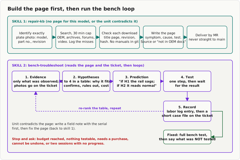
The two skills as one flow. The dashed line is the loop.
The lead case: an HP 3458A
The HP 3458A is a bench multimeter from 1989 with 8.5 digits of resolution. This one fails its power-on self-test with RAM TEST 1 LOW and an error light. My bench tech and I had not touched one before.
What the knowledge base found
Claude pulled HP’s own component-level documentation set into the repo: the board component locator, the A5 controller schematic, and four service notes. It did not exist anywhere on disk before. The ticket had been written from forum posts and memory. Reading the primary sources corrected the ticket three times:
- Chip select. The two memory chips are a high-byte and low-byte pair. I assumed they share everything. They do not share the chip enable pin, which is the byte lane select. Continuity between the two sockets on that pin should read open, and a naive check would have called that a fault.
- HP’s service note on this repair says a full calibration is required after replacing the RAM chips, including the calibration RAM. The schematic suggests the calibration constants live in a separate chip, so they should survive. Both are citable. My original resale thesis (“cal survives, cheap chip swap”) leaned on the optimistic reading. The page now says: do not call the meter calibration intact.
- The cal dump method was unverified. The ticket said to read the calibration RAM by issuing 2048
MREADcommands from a given address. That command is not in the 375-page user’s guide, and nothing corroborated the address range.
The pin-1 orientation was settled the same way. HP’s drawing puts the pin-1 marker on the same edge for the memory chips and the EPROMs next to them. The EPROM has a physical notch you can see without disassembly, so it works as a free reference on the bench.
The fix so far
The fault is the battery-backed static RAM pair. Their embedded cells are end of life in a 1989 meter. I replaced both with FRAM, which keeps its contents without a battery. FRAM only comes in surface-mount packages, so each chip sits on a small adapter that plugs into a machined socket I soldered onto the board in place of the old chip.

The adapters beside the empty sockets before seating. The labelled EPROMs above are the pin-1 reference.
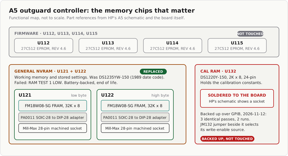
The same board by job. Functional map, not to scale.
After seating them, the meter booted. The only error was 114 SYSTEM ERROR, which I read as a first boot on blank memory. A power cycle passed the self-test and the error stayed clear. With the front input shorted it read about 8 microvolts, cold, covers off.
The Prologix wedge
The calibration chip is the one part I cannot afford to lose. It is a 1989 battery-backed part that holds the constants, and HP’s schematic shows it socketed. On this unit it is soldered to the board. I found that on the bench, and it changed the plan immediately: no desoldering until the contents are backed up.
So the backup goes over GPIB, through a Prologix GPIB-USB adapter. Claude wrote the script and made it read-only by construction. Every command passes through one function that refuses anything not on a short allowlist of queries, so no code path can send a calibrate or write command. It reads all 253 calibration constants, factory and present, and a raw image of the chip, and saves the image only when three passes agree.
It tested clean against a simulator. Then it met the real meter and wedged the adapter.
The reason is the detail I enjoyed most. At power-on the 3458A is in END OFF and TRIG AUTO. It free-runs readings and does not mark the end of a message. The Prologix ++read eoi waits for an end-of-message marker that never comes, so the read never finishes and the adapter locks. The first version of the script also misread the free-running meter, which is the fix MR !993 carries.
The fix in the script is to send a device clear, then TRIG HOLD and END ALWAYS before any read, drain whatever is still arriving, and use ++read 10, which stops at a line feed. If the adapter wedges anyway, you unplug its USB lead for five seconds and power-cycle the meter.
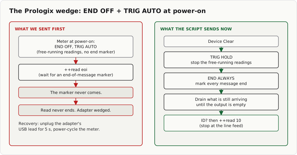
The first read, and the sequence the script sends now.
On 2026-11-12 it worked. Two runs of three passes each produced the same 2048-byte image, with the calibration counter reading 2 before and after. As a sanity check, 24 of the stored constants also appear verbatim inside the image as 64-bit numbers, so it is the real memory and not noise.
Where it stands
Not done. Next is the warm-up and the meter’s own auto-calibration, then another backup as the new reference. After that I decide whether to replace the calibration chip with FRAM too, using the verified image as the way back, or leave the original and keep the backup with the meter. The write program for that swap is not written yet. I do not have a calibrated meter yet and I will not call it one.
Where the AI was wrong
This is the section to read if you are thinking of doing the same thing.
- The 3458A plan had a made-up cal-dump method.
MREADover a specific address range was in the ticket as fact. It was a plausible-looking recipe from a forum fragment. The verification step caught it, and the final method (CAL?queries plus theMREADimage, with three agreeing passes) was proven on the real meter before I trusted it. - The chip part number was wrong. The notes said DS1230. Photos of the board showed DS1235YW. They are pin compatible, so nothing broke, but the record now says what is on the board.
- The adapter pins were the wrong part, twice. The adapters I bought ship with square gull-wing pins that do not fit the machined sockets. I only learned that after the sockets were soldered in. The first suggested fix, a through-hole round-pin breakaway header, was also wrong, because the adapter pads are surface mount. The right part is a surface-mount round-pin header.
- The test sketch had a glitch that faked a failure. On an AVR board, setting a pin to output drives it low until the next write lands. On a memory bus, chip enable low plus write enable low is a complete write cycle. The test sketch wrote a garbage byte to address 0 on every reset, so a good chip would report one mismatch and look dead. Found by reading, fixed, and checked with a simulation of the register behaviour.
- A needed file lived in a scratch directory. The ticket referenced the test sketch by name for four days. It existed only in an agent’s temp folder that got cleaned up. Claude recovered it from the session transcript. The rule since then: an artifact that matters goes in the repo in the session that creates it.
- A balance doc said the opposite of the manual. On the analytical balances, a repo doc claimed the AG204 has no automatic internal calibration weight. The OEM manual lists it for every model in the line. In the same ticket, the error-code list was shifted by one, so “Error 4” was described as a missing pan when it is an internal fault. A “4-pin versus 3-pin power” discrepancy turned out to be the manual’s peripheral port, not the power inlet. The ticket carries a dated correction block, and I keep corrections next to the mistake instead of deleting it.
- A controller we own cannot drive the pump. For the HPLC modules, an early version of the plan counted the degasser tickets as unlocked by the handheld controller we bought. They are not, and per Agilent’s own guide that controller cannot drive the binary pump SL either. The page now says so near the top.
Where the bench work mattered
A missing needle. An HPLC autosampler had been closed as tested, and its condition notes and photo captions all said the needle assembly was present. When the person on the bench looked at it directly, the needle seat was there and the needle was not. The module’s own injector test could not have caught that: it has no needle sensor, and the arm moves and reports success regardless. The follow-up ticket lists two explanations it could not yet tell apart: the earlier caption recorded an assumption as an observation, or the needle went missing while the unit was being moved around. Either way, neither the model nor the checklist could look at the part.
The same goes for the 3458A. The soldered calibration chip, the cut-and-clear desoldering, the collet fit, the first-boot behaviour: these are hands and eyes. The knowledge base makes my hands better aimed. It does not replace them.
Three shorter examples
HPLC modules. The page opens with what you need before you can test anything: the modules have no keypad, so a controller is mandatory, and it has to be one that can drive that module. It also records that a lot of “fittings” I received turned out to be gas chromatograph consumables, none of which will cap a pump outlet at HPLC pressures, so the pressure-hold step waits for a real stainless blanking plug.
Vacuum pumps. The page’s best line is that the gauge decides the grade. A dial gauge cannot grade a rotary vane pump, so a pump without a proper gauge is listed as “powers on, pulls vacuum, not graded”. It also had the gotcha that one model will not start without a jumper on its control port. Two pumps of the same model were tested back to back: one reached 30 mTorr and the older one 35, against a spec of 37.5. The older one’s margin is thin, so its listing quotes the measured number instead of saying “meets spec”.
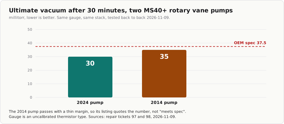
Same gauge and stack for both. The gauge is an uncalibrated thermistor type, so read it as a comparison, not a certificate.
Analytical balances. A table separates two models that look identical on a shelf but have different readability. It exists to stop me titling a listing with a precision the unit does not have.
What I have not got
I would like to say Claude drew me exploded diagrams of each machine. It did not. What exists is the text pages in the repo, the per-model bench-test docs with their tiers, the case files on each ticket, and the reference folder for the 3458A. The pictures in that folder are HP’s own drawings, cropped to the part that proves one point, such as the pin-1 marker. They are HP’s, so they stay in the repo and not on this blog. The photo above is mine.
What I would tell you
- Make the knowledge base a deliverable. A page that lives in the repo and cites its sources is something you can check and correct. A summary in a chat is not.
- Require “not in OEM docs” as a legal answer. It is the cheapest hallucination filter I have found.
- Put the prediction before the test. It stops the model, and me, from reading every result as support.
- Keep the case file short and keep it on the ticket. A session that starts cold reads one page and knows where things stand.
- Treat the thing that cannot be undone as its own step, with its own backup, before any other step.